By Oko
Founder, Offshore Pipeline Insight
March 13, 2026
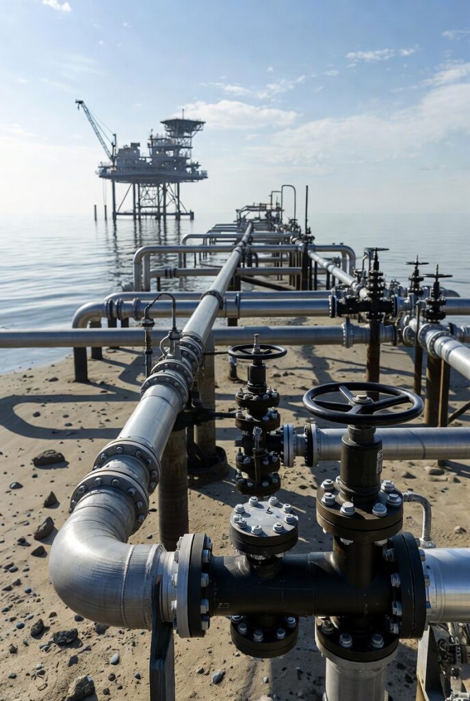
Carbon Capture and Storage (CCS) continues to gain momentum in the offshore sector, with subsea CO₂ injection systems playing a pivotal role in enabling safe, large-scale permanent sequestration. These systems deliver captured CO₂ (typically in dense supercritical or liquid phase) from capture points through subsea pipelines to injection wells in depleted reservoirs or saline formations. Real-world progress in 2026 includes Northern Lights (Norway) achieving operational status, Porthos (Netherlands) ramping up, and multiple North Sea expansions demonstrating adapted subsea hardware.
This technical overview covers subsea injection system architecture, offshore CCS pipeline design considerations, and the engineering strategies for repurposing depleted hydrocarbon fields essential knowledge for pipeline integrity, subsea, and CCS professionals.
Subsea CO₂ Injection Systems: Architecture and Key Components
Subsea injection adapts mature oil & gas technology (e.g., Christmas trees, manifolds, flowlines) to CO₂’s distinct properties: supercritical behavior above critical point (31.1°C, 73.8 bar), potential corrosivity from impurities (water, H₂S, O₂ forming acids), and risks like phase transition, hydrate formation, or Joule-Thomson cooling.Core elements include:
- Subsea Injection Trees & Manifolds: Modified production trees with corrosion-resistant alloys (e.g., Inconel 625 overlays, duplex stainless) and materials qualified for CO₂ service. Trees control injection rates and provide isolation.
- Umbilicals & Control Systems: Deliver power, hydraulics, methanol/inhibitors, and fiber-optic monitoring for pressure, temperature, and distributed acoustic sensing.
- Flow Assurance: Insulation or active heating to maintain dense phase; chemical injection points for corrosion control.
- Monitoring & Verification: Downhole gauges, 4D seismic, seabed gravimetry, and leak detection for plume tracking and regulatory compliance.
Northern Lights Phase 2 (2025 contract to OneSubsea) delivers satellite injection systems with tie-ins, expanding capacity beyond Phase 1’s Aurora reservoir (2,600 m depth, >1.5 Mtpa initial).Real-world example from Northern Lights expansion subsea CO₂ injection equipment assembly:Here is the Northern Pioneer vessel, central to Northern Lights’ ship-based CO₂ transport and offshore offloading:Conceptual overview of the Northern Lights CCS chain, from capture to subsea storage:
Offshore CCS Pipeline Design: Technical Challenges and Solutions
Offshore CO₂ pipelines transport dense-phase CO₂ over tens to hundreds of kilometers, often repurposed from existing gas lines or newly laid. Design differs significantly from hydrocarbon service due to CO₂’s density, corrosivity, and fracture risks.
Critical design aspects:
- Phase Management: Maintain supercritical state to avoid two-phase flow; dehydration to <50 ppm water prevents corrosion and hydrates.
- Materials & Corrosion: Internal CRA linings or inhibitors for wet CO₂; external 3-layer polyethylene + cathodic protection. Impurity specs (e.g., ISO 27914) dictate alloy selection.
- Fracture & Integrity: High toughness steel to arrest running ductile fractures (per DNV-RP-F104); fatigue analysis for cyclic pressure from injection.
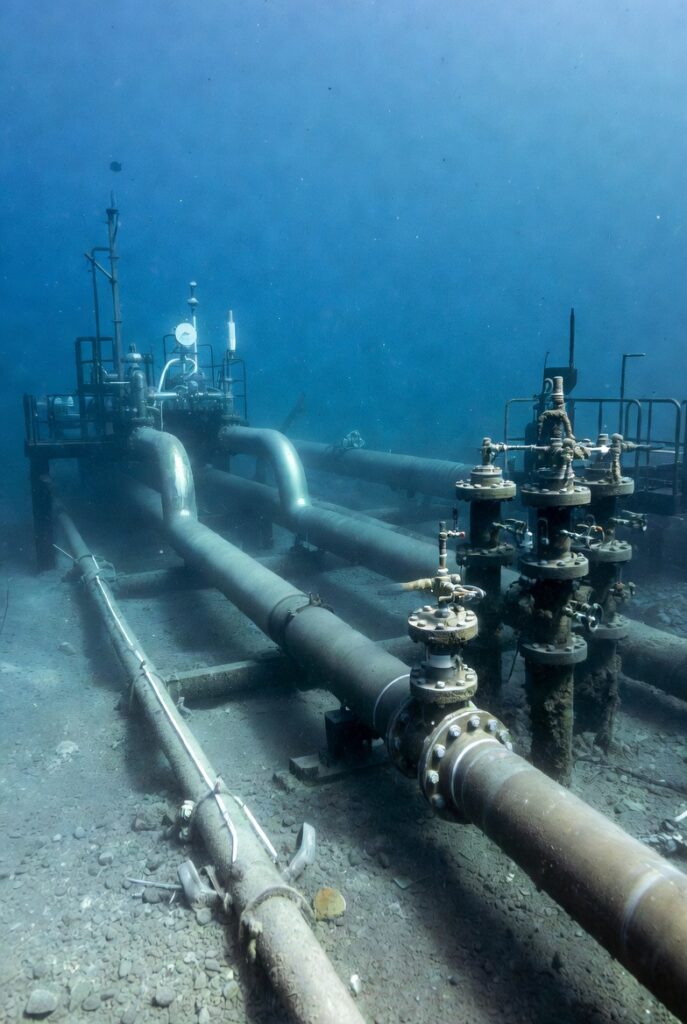
- Installation & Routing: S-lay or J-lay from pipelay vessels; burial for protection; dynamic sections near platforms require flexible risers or jumpers.
- Repurposing: Integrity assessments (pigging, pressure testing, ILI) confirm compatibility; cleaning removes hydrocarbons/residues.
Pipelay operations for offshore lines (applicable to CCS export pipelines):
Repurposing Depleted Fields for Carbon Storage
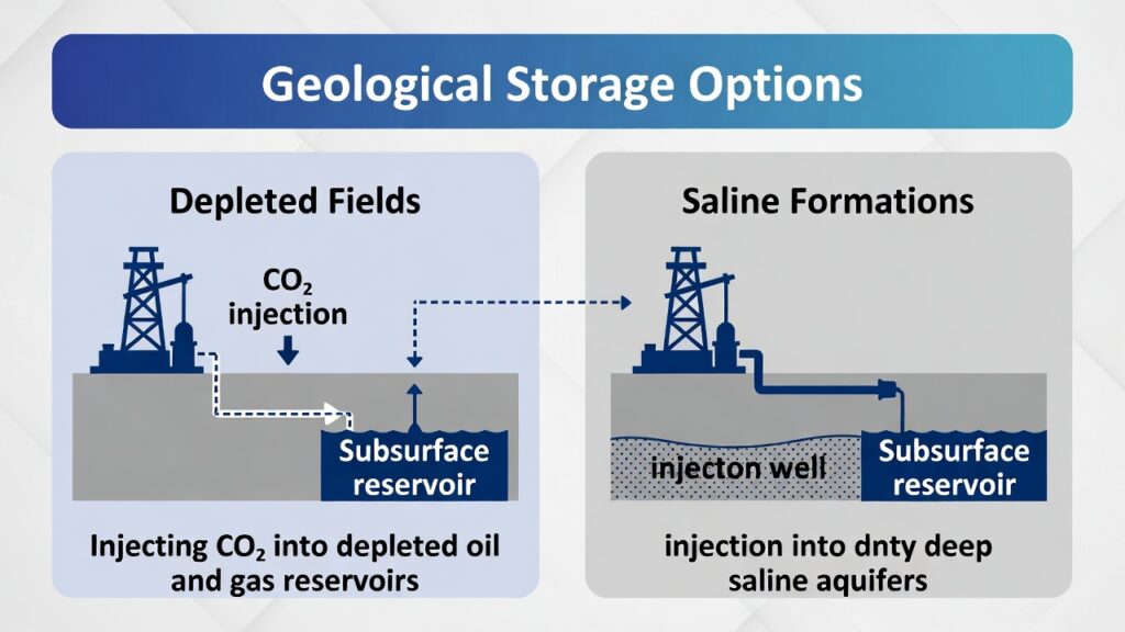
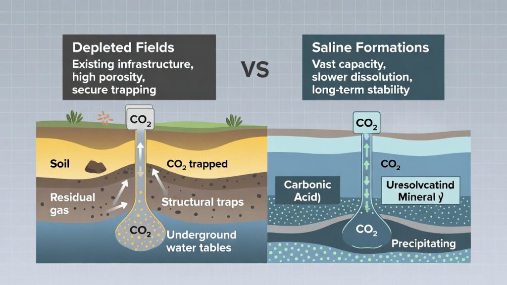
Depleted fields provide ideal storage sites: proven caprock seals, extensive subsurface data from production history, and existing wells/infrastructure reducing exploration risk and costs.
Technical considerations:
- Reservoir Suitability: Target sandstone or carbonate formations with sufficient pore volume and injectivity; pressure management to stay below fracture gradient.
- Well Conversion: Re-complete or sidetrack production wells; install new barriers (cement with CO₂-resistant additives) to prevent leakage.
- Injection Strategy: Phased injection with monitoring; potential CO₂-EOR for incremental recovery before pure storage.
- Risk Mitigation: Geomechanical modeling for induced seismicity; continuous plume surveillance.
Geological storage options, highlighting depleted fields as primary choice:Schematic illustrating CO₂ injection into depleted reservoirs vs. saline formations:
Implications for Offshore Pipeline and Subsea Professionals
Subsea CO₂ systems and repurposed infrastructure represent a major opportunity to extend legacy asset value into the energy transition. Key focus areas include material qualification for CO₂ service, integrity management during repurposing, and hybrid monitoring solutions.For offshore pros:
How are you preparing pipelines and wells for CO₂ service?
Share your experiences or challenges in the comments let’s advance the conversation!