By Oko
Founder, Offshore Pipeline Insight
March 16, 2026
In the evolving landscape of offshore oil and gas engineering, subsea modeling plays a pivotal role in optimizing designs, ensuring safety, and enhancing operational efficiency. Halliburton’s Landmark suite, including Compass for well trajectory planning, and Schlumberger’s Petrel for subsurface reservoir modeling, provide powerful platforms for integrating advanced simulation techniques like Computational Fluid Dynamics (CFD) and Finite Element Analysis (FEA). This technical blog explores the application of CFD for wellbore modeling and FEA for subsea connectors, highlighting how these tools address HPHT challenges and regulatory demands in subsea environments.
CFD for Well bore Modeling in Subsea Operations : CFD is essential for simulating fluid flow, heat transfer, and multiphase dynamics in well bores, particularly in subsea HPHT settings where pressure exceeds 15,000 psi and temperatures surpass 350°F. Using Petrel subsurface software, engineers can create integrated models that couple reservoir, wellbore, and surface flows.Petrel enables seamless data import from seismic and well logs, facilitating CFD simulations to predict phenomena like annular pressure buildup (APB), cuttings transport, and hydrate formation. For instance, in riserless subsea pipelines, CFD-DEM coupling models cuttings bed erosion, as shown in recent studies.
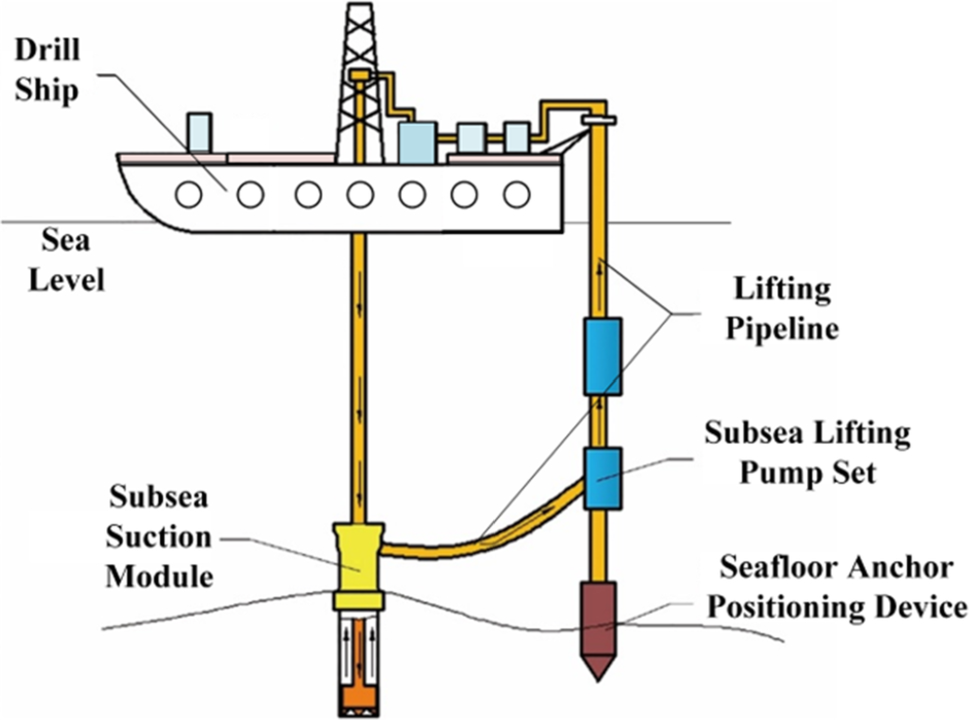
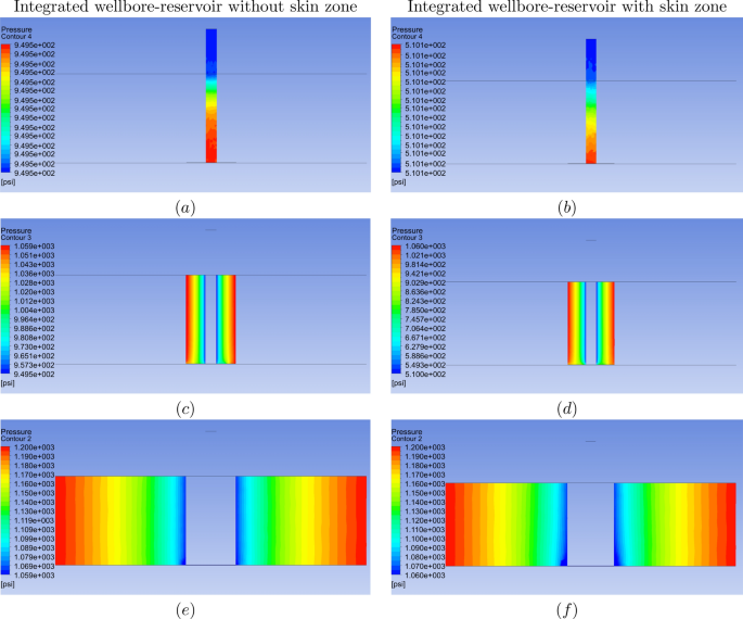
Another example is integrated wellbore-reservoir modeling using 3D Navier-Stokes equations, where CFD solvers reveal pressure distributions with and without skin zones, aiding in stimulation design.
Landmark’s Compass complements this by optimizing well trajectories, incorporating CFD outputs to minimize torque and drag in complex subsea paths. Economics improve through reduced NPT and enhanced recovery, with simulations cutting design iterations by 30–50%.
FEA for Subsea Connectors
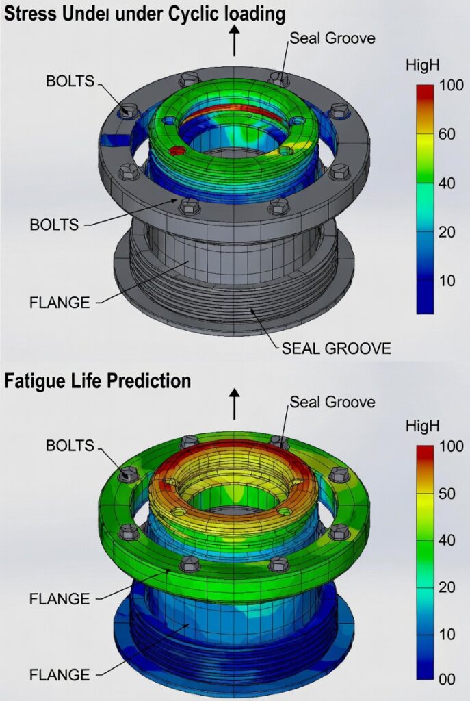
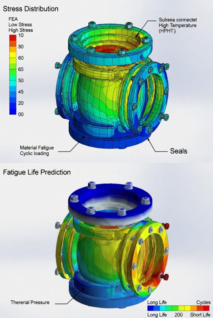
Subsea connectors, critical for tying back wells to manifolds and risers, must withstand extreme loads. FEA in Landmark or Petrel models stress, strain, and fatigue in connectors, ensuring compliance with BSEE and API standards.FEA simulates bolt preload, seal integrity, and thermal expansion in HPHT connectors, predicting failure modes like galling or leakage. Petrel’s geomechanical modules integrate FEA with reservoir data for full-field analysis, while Compass handles connector placement in well planning.Visuals from studies show FEA stress distributions in subsea connectors under cyclic loading.These techniques reduce CAPEX by optimizing materials (e.g., high-alloy steels) and OPEX through predictive maintenance.
Petrel for Integrated Subsea ModelingPetrel provides a unified platform for subsurface and wellbore modeling, supporting seismic interpretation, reservoir simulation, and geomechanics. For subsea HPHT fields, Petrel excels in:
- Building high-resolution geological models.
- Coupling reservoir and wellbore dynamics.
- Importing real-time data for history matching and forward simulation.
Petrel’s well and completion design module allows complex geometries, incorporating HPHT-specific materials and barriers.
Computational Fluid Dynamics (CFD) for Wellbore Simulation CFD is essential for modeling multiphase flow, heat transfer, and pressure behavior in HPHT wellbores. Petrel integrates with CFD solvers (e.g., ANSYS Fluent, OLGA, or in-house tools) to simulate:
- Annular pressure buildup (APB) due to thermal expansion.
- Cuttings transport and hole cleaning in deviated subsea wells.
- Hydrate formation and multiphase flow regimes (bubble, slug, churn).
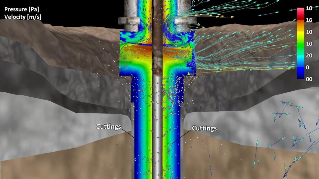
In HPHT subsea environments, CFD predicts transient pressure drops, erosion risks, and fluid rheology effects under extreme conditions (>15,000 psi, >350°F). Studies show CFD-DEM coupling accurately models cuttings bed erosion in riserless operations, reducing NPT by optimizing mud properties and flow rates.
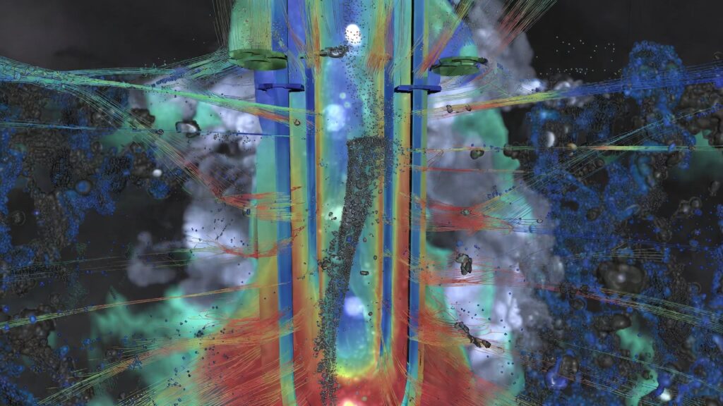
Visual: CFD simulation of multiphase flow in an HPHT well bore, showing pressure distribution and cuttings transport.Another example: CFD results for well bore flow with and without skin zones, highlighting pressure anomalies critical for stimulation design.
Finite Element Analysis (FEA) for Subsea Connectors
Subsea connectors (e.g., wellhead, flow line jumpers, manifolds) must withstand cyclic loading, thermal expansion, and corrosion in HPHT conditions. FEA (using ANSYS, Abaqus, or Petrel-integrated modules) evaluates:
- Stress/strain in seals, bolts, and housing.
- Fatigue life under pressure/temperature cycling.
- Seal integrity and galling risks.
API 17TR8 and BSEE require independent third-party FEA verification for HPHT connectors, ensuring design margins for extreme loads. FEA predicts failure modes like crack propagation or leakage, optimizing materials (e.g., Inconel overlays, duplex stainless steel).
Visual: FEA stress distribution in an HPHT subsea connector under cyclic loading, showing high-stress zones in bolts and seals.Another view: FEA model of subsea connector fatigue life prediction, illustrating thermal and pressure effects.
Economic and Operational BenefitsUsing COMPASS for trajectory optimization and Petrel for reservoir/wellbore modeling reduces design iterations by 30–50%. CFD and FEA minimize risks:
- CFD cuts NPT from poor hole cleaning or kicks.
- FEA extends connector life, reducing intervention costs ($5–20 million per subsea repair).
These tools align with BSEE regulations, improving economics through safer, more reliable HPHT developments.For subsea engineers: How are you integrating CFD/FEA in your HPHT projects? Share your experiences!