Explore HPHT deepwater pipeline design challenges, material selection, thermal stress analysis, and structural integrity strategies for extreme offshore conditions.
High-Pressure High-Temperature (HPHT) pipelines in deepwater environments represent one of the most technically demanding applications in offshore oil and gas infrastructure. Defined broadly as systems operating above 10,000–15,000 psi (690–1,034 bar) and 300–350°F (149–177°C), with ultra-HPHT projects now regularly exceeding 20,000 psi and 350°F, these pipelines must reliably transport hydrocarbons from subsea wells to floating production units or export risers over distances that can exceed 50 km in water depths greater than 1,500 m.As of early 2026, active ultra-HPHT developments in the Gulf of Mexico (Anchor, Shenandoah, Monument, Ballymore), Brazil pre-salt fields, and emerging West Africa and North Sea projects continue to drive technology forward. Yet the combination of extreme pressure, temperature, water depth, and cyclic loading creates a uniquely hostile operating envelope. This article examines the principal engineering challenges, material selection strategies, and stress/strain considerations that dominate HPHT pipeline design in deepwater.
1. Principal Design Challenges in Deepwater HPHT Pipelines1.1 Thermal Expansion and Global BucklingReservoir fluids at 350–450°F enter the pipeline cold (seawater ~4°C at depth), then heat rapidly during start-up. The resulting thermal expansion generates axial compressive force that can exceed the pipe’s Euler buckling resistance, leading to lateral or upheaval buckling.In deepwater, where pipelines are usually laid unburied on soft seabed soils, lateral buckling is the dominant mode. Uncontrolled (rogue) buckles can produce localized strains >0.5–1%, risking local buckling, weld fatigue, or upheaval if the pipe lifts off the seabed.Key parameters influencing buckling risk:
- Temperature differential (ΔT) during operation
- Axial force build-up (P = E·A·α·ΔT, where α is the thermal expansion coefficient)
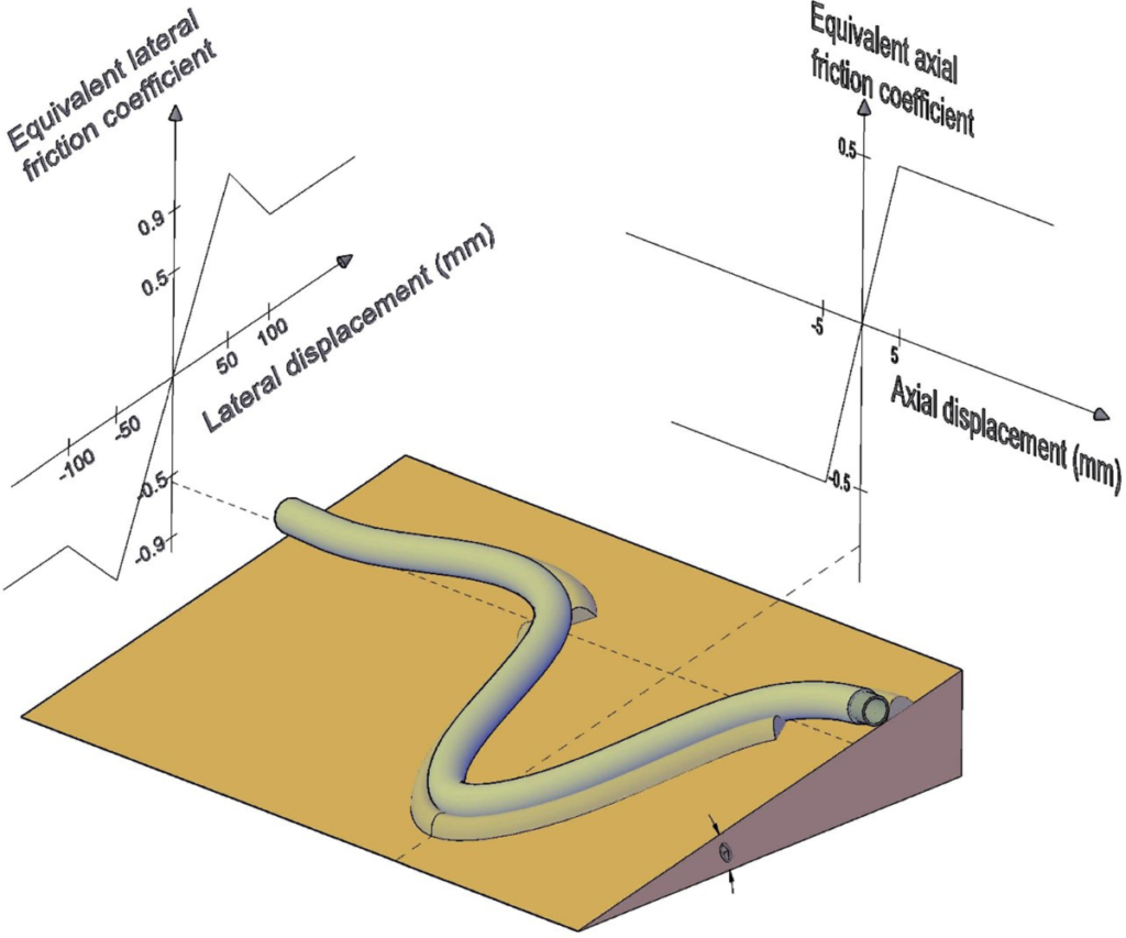
- Pipe-soil interaction (friction factor typically 0.4–0.6 on clay)
- Out-of-straightness from lay process (residual curvature)
1.2 Pipeline WalkingRepeated thermal/pressure cycles cause ratcheting axial displacement (“walking”) toward the hotter end of the flowline. Walking distances of several meters per year have been observed in some North Sea and GoM systems, leading to:
- Over-stress at risers and end connections
- Misalignment at spool tie-ins
- Fatigue accumulation at welds and risers
Walking is exacerbated in HPHT systems by large thermal gradients and low effective axial friction on deepwater seabeds.1.3 Fatigue and Fracture at BucklesGlobal buckles act as strain concentrators. Cyclic loading from shut-down/start-up, pigging, and flow variations drives low-cycle fatigue at the buckle crown and sag-bend regions. Girth welds in these locations are particularly vulnerable if misalignment or high-low exceeds tolerances.1.4 External Pressure Collapse and Propagating Ductile FractureIn deep water (>2,000 m), external hydrostatic pressure can exceed internal design pressure during hydrotest or shut-in. Collapse resistance must be demonstrated per DNVGL-ST-F101 or API RP 1111, often requiring increased wall thickness or ring stiffeners.Ultra-high-strength line pipe (X80–X100) used to reduce wall thickness is susceptible to running ductile fracture if toughness is inadequate.2. Material Selection for Deepwater HPHT PipelinesMaterial choice balances strength, temperature de-rating, corrosion resistance, weldability, and cost.2.1 Carbon-Manganese Line Pipe
- Grades X65–X80 are common.
- Yield strength de-rates significantly above 150–200°C (per API 5L and DNVGL-ST-F101 annex).
- Maximum allowable temperature typically limited to 150–180°C unless qualified with full-scale testing.
2.2 Corrosion-Resistant Alloys (CRA) & Clad/Lined Pipe
- For CO₂/H₂S-containing fluids, solid CRA (e.g., 316L, 22Cr duplex, 25Cr super-duplex) or mechanically lined/clad pipe (carbon steel carrier + CRA liner) is required.
- Clad pipe is usually more economical than solid CRA for long tie-backs.
- Girth welding of clad pipe requires careful procedure qualification to avoid dilution and cracking.
2.3 Mechanically Lined vs. Metallurgically Clad vs. Solid CRA
- Mechanically lined: Cost-effective, but liner wrinkling risk during reeling/installation.
- Metallurgically clad: Excellent bond integrity, higher cost.
- Solid CRA: Highest integrity, highest cost, used for short, severe-service sections.
2.4 Qualification RequirementsHPHT pipelines require enhanced qualification beyond standard API 5L:
- Full-scale burst/collapse testing
- High-temperature tensile testing
- Girth weld fatigue testing
- Strain capacity testing (for reeling and buckling scenarios)
3. Stress and Strain Design Considerations3.1 Limit State Design ApproachModern HPHT design uses DNVGL-ST-F101 limit-state methodology with four limit states:
- ULS (Ultimate) — pressure containment, local buckling
- ALS (Accidental) — extreme events
- SLS (Serviceability) — deflection limits
- FLS (Fatigue) — cyclic loading
Design factor on hoop stress is typically 0.72 (DNVGL) or 0.60–0.72 (ASME B31.8), but strain-based criteria are frequently applied where displacement-controlled loading dominates (e.g., thermal expansion).3.2 Strain-Based DesignWhen displacement is controlled (buckling, reeling, installation), the design shifts from stress-based to strain-based criteria.
- Allowable strain limits: typically 0.4–1.0% for tension, 0.15–0.3% compression (depending on safety class and code).
- FEA modeling (ABAQUS, ANSYS) is standard to predict local strain concentrations at buckles and welds.
3.3 Fatigue AssessmentS-N curves (DNVGL-RP-C203) combined with rainflow counting of stress cycles. Critical locations: buckle crowns, sag-bends, girth welds. Safety factors on fatigue life typically 10.3.4 Installation and Reeling ConsiderationsReeling onto a reel-lay vessel induces plastic strain (up to 2–3%). Material must demonstrate adequate strain aging resistance and post-reeling toughness.SummaryDesigning deepwater HPHT pipelines requires an integrated approach addressing thermal buckling, walking, material de-rating, fatigue, and collapse. The most successful projects combine:
- Advanced limit-state and strain-based design codes
- High-quality material qualification
- Detailed FEA modeling of buckle formation and fatigue
- Real-time integrity monitoring (fiber-optic sensing, strain gauges)
- Rigorous installation analysis
Engineers with field experience know that many failures originate from oversights in early modeling or material qualification. Investing upfront in these areas remains the most cost-effective way to ensure long-term integrity in ultra-HPHT deepwater systems.For practical tools, checklists, and calculators to support HPHT pipeline design and integrity management, visit the free downloads section at OffshorePipelineInsight.com.
Oko Immanuel
Subsea & Offshore Pipeline Engineer | Former Roughneck | Texas A&M Petroleum & Subsea Engineering