Oko Immanuel
Petroleum / Subsea Engineer
Founder, Offshore Pipeline Insight
March 05, 2026
As floating offshore wind (FOW) scales toward commercial arrays in deeper waters, two interconnected engineering challenges stand out: ensuring long-term integrity of dynamic power cables under cyclic loading, and leveraging high-capacity-factor wind resources for efficient green hydrogen production at or near the platform. These topics intersect meaningfully dynamic cables transport power from turbines to hubs (or directly to electrolyzers in integrated concepts), while hydrogen pathways can reduce reliance on long export cables, mitigate grid constraints, and create new revenue from stored/exported energy vectors.
This blog examines both areas technically, drawing from recent 2025–2026 studies, guidelines, and project insights.
1. Dynamic Cable Fatigue: Mechanisms, Analysis, and Design ChallengesDynamic power cables in FOW connect floating turbines or substations to the seabed or inter-array systems, enduring continuous bending, tension, torsion, and hydrodynamic forces from platform motions, waves, currents, and offsets. Unlike static seabed cables, dynamic sections experience high-cycle fatigue, primarily in metallic components (armor wires, conductors) and polymer layers (insulation, sheaths).
Key Fatigue Mechanisms
- Mechanical fatigue: Repeated curvature and tension cycles cause cumulative damage in copper conductors (stranded compaction affects local stress), steel armor wires (torsional fatigue from twisting), and water barriers (cracking under strain).
- Electrical aging synergy: Moisture ingress + electrical stress accelerates water/electrical treeing in insulation; mechanical strain exacerbates partial discharges and tree growth, shortening time-to-failure.
- Environmental factors: Abrasion at touch-down, corrosion, and thermal cycling compound damage.
Failure modes include conductor wire breaks, armor fatigue fractures, insulation breakdown, and loss of water tightness (critical for “dry” designs with lead barriers).
Fatigue Analysis Methods
Modern approaches combine:
- Global analysis: OrcaFlex, Riflex, or MoorDyn simulations of lazy-wave, steep-wave, or W-shaped configurations under ULS (ultimate), ALS (accidental), and FLS (fatigue) limit states. Key outputs: hang-off tension, minimum bend radius (MBR), curvature range, and cumulative fatigue damage.
- Local analysis: Finite element models assess stress concentrations in armor wires, conductors, and insulation under combined tension-bending-torsion.
- S-N curves and Palmgren-Miner rule: Fatigue life prediction uses component-specific S-N data (e.g., for armor wires) with design fatigue factors (DFF) often 3–10, calibrated for safety.
- Probabilistic reliability: Monte Carlo or response surface methods quantify uncertainty in environmental loads and material properties.
Recent guidelines (e.g., Carbon Trust Floating Wind JIP “Guidance for Dynamic Cables,” 2025 update) emphasize best practices: cross-industry standards review, combined mechanical-electrical testing, and holistic early-design methodologies. For 15 MW reference turbines (e.g., NREL/UMaine semi-sub), lazy-wave optimization balances buoyancy modules (DBMs) to minimize hang-off tension (~30% MBL) while meeting MBR (>490–1100% nominal) and Ez angle criteria.
This diagram illustrates a typical lazy-wave dynamic cable configuration with distributed buoyancy modules, bend stiffeners, and key fatigue-critical sections:Another schematic compares lazy-wave vs. steep-wave layouts, highlighting motion and fatigue implications in deep water:
Challenges persist in deep water (>1000 m), higher voltages (145–320 kV), and floater-specific motions ongoing JIPs focus on calibration of utilization factors and new water-barrier tech for robustness.
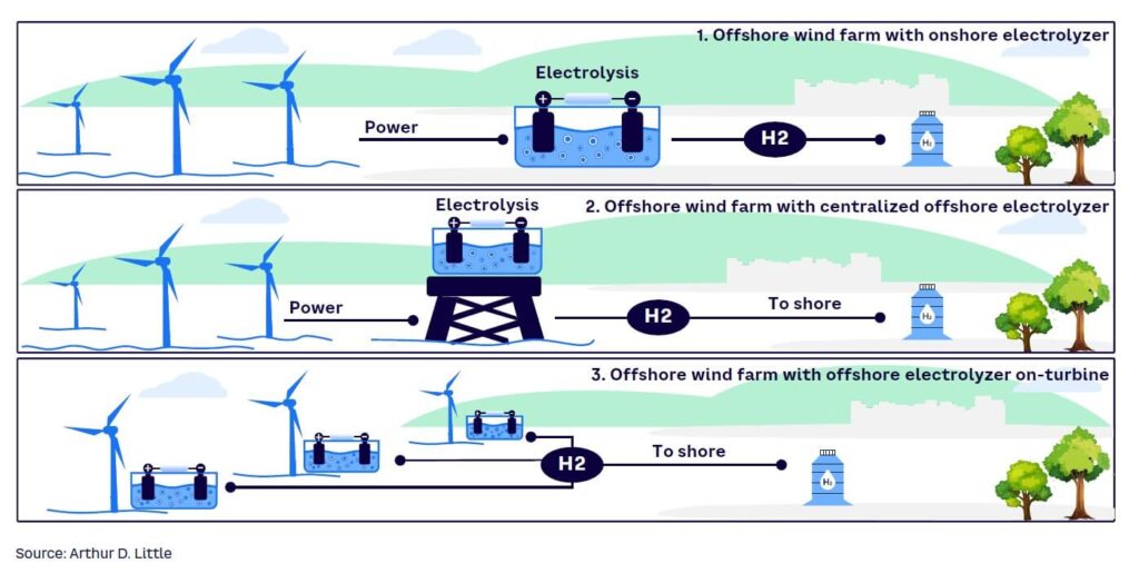
( Integration models for offshore wind and green hydrogen production: onshore, centralized offshore, and turbine-integrated electrolysis. (Source: Arthur D. Little, Offshore Wind & Hydrogen Integration).”
2. Synergies: Green Hydrogen Production from Floating Offshore Wind
Offshore green hydrogen (via PEM or alkaline electrolysis) uses surplus or dedicated wind power to split seawater (desalinated) into H₂ and O₂, addressing curtailment, grid congestion, and transmission losses. Floating platforms enable this in deepwater sites with capacity factors of 60–70% (vs. 30–40% onshore), unlocking economical H₂ at scale.
Integration Models
- Centralized on-platform: Electrolyzers + compression/storage on floating substation or dedicated “energy island” platforms; H₂ piped ashore or to ships (e.g., ammonia/LOHC carriers).
- Turbine-integrated: Direct electrolysis in/near nacelle (e.g., H2Mare HT1 trials); minimizes cable needs but adds platform mass/motion complexity.
- Hybrid: Partial power export via dynamic cables + on-site H₂ for buffering; subsea storage (compressed H₂ or carriers) enhances utilization.
Benefits include:
- High wind consistency → steady electrolyzer load (80%+ utilization).
- Avoid long HV export cables → reduce capex and dynamic fatigue exposure.
- Decarbonization vectors: H₂ for industry, shipping bunkering, or reconversion to power.
- Economic upside: LCOH reductions via scale, learning curves, and avoided grid upgrades.
Techno-economic studies show promising LCOH in high-wind regions (e.g., Celtic Sea, US West Coast, Peru Ica coast adaptations). Projects like Lhyfe’s floating demo (Saint-Nazaire) and concepts for semi-sub platforms demonstrate feasibility.
This conceptual diagram shows an integrated floating wind-hydrogen system with on-platform electrolysis, compression, and export options:
A global map highlights prime deepwater sites for floating wind + H₂ synergies:
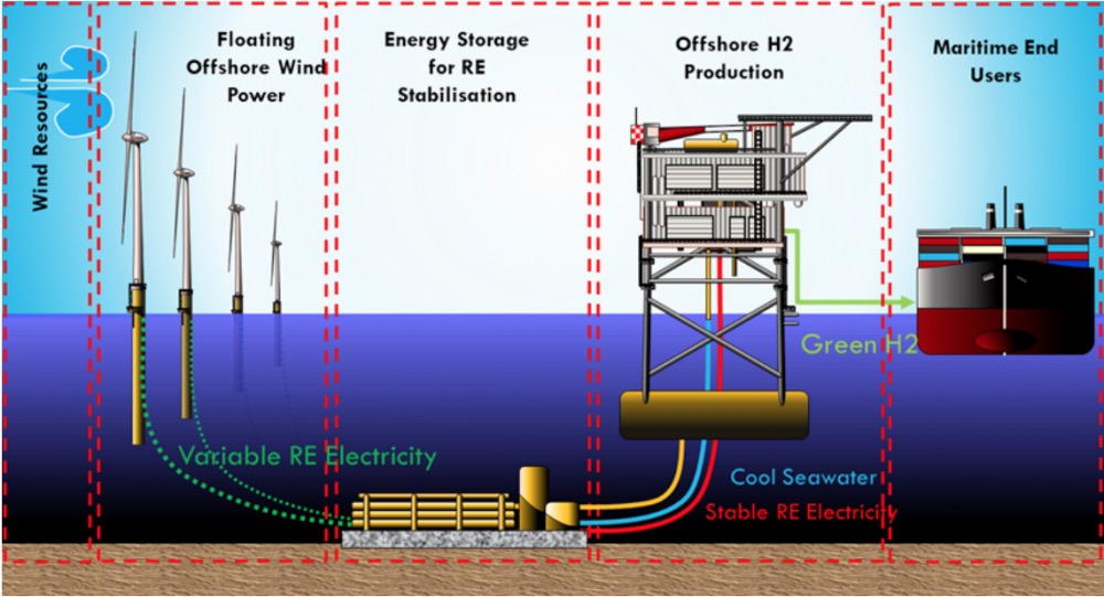
Conceptual integrated system: Floating offshore wind powering energy storage and offshore green hydrogen production, with export pathways for H₂ (e.g., via pipeline or carrier). (Source: Malta offshore H₂ study).”
Cross-Synergies and Pipeline Relevance: Hydrogen pathways reduce dynamic cable lengths/exposure → lower fatigue risk. Repurposed O&G pipelines enable H₂/CO₂ transport from hubs. Subsea storage buffers variability, extending electrolyzer life. As a subsea engineer, I see direct tech transfer: mooring integrity, dynamic umbilicals/cables, and flow assurance principles apply to H₂ systems.
Closing Thoughts
Dynamic cable fatigue remains a critical path for FOW reliability advances in analysis, testing, and guidelines are closing gaps, but deepwater/high-voltage deployments demand continued innovation. Pairing with green H₂ production amplifies value: higher asset utilization, reduced infrastructure strain, and scalable decarbonization.
These areas offer rich opportunities for subsea/pipeline expertise in the energy transition. Interested in specifics like lazy-wave optimization code snippets, H₂ pipeline compatibility, or project case studies?
Oko Immanuel
Petroleum / Subsea Engineer
Founder, Offshore Pipeline Insight.
March 05, 2026