By Oko Immanuel, M.Eng – Founder, Offshore Pipeline Insight
March 20, 2026Carbon Capture and Storage (CCS) is no longer optional for LNG projects — it’s a regulatory and commercial necessity in 2026. With new methane fees, EU CBAM, buyer demands for low-carbon LNG, and investor ESG pressure, operators are embedding CCS into feed-gas processing, offshore infrastructure, and even hybrid floating wind + LNG/CCS hubs. Subsea technology is the key enabler for safe, efficient CO₂ transport, injection, and long-term storage.
This article dives deep into subsea tech (pipelines, compression, injection systems, monitoring), logistics challenges, and real-world case studies from Qatar NFE, Mozambique LNG, Northern Lights (Norway), Porthos (Netherlands), and floating wind synergies.
1. Subsea Technology Driving CCS in LNG & Floating Wind
Subsea systems handle the toughest parts of CCS: transporting dense-phase CO₂ offshore, injecting into reservoirs, and ensuring long-term containment.
Key subsea technologies in 2026:
- CO₂ Pipelines & Flow lines : CRA-lined or pipe-in-pipe (PIP) for corrosion resistance (CO₂ + impurities) and thermal insulation to maintain supercritical state. Rated 100–200 bar for injection.
- Subsea Compression & Boosting : Compact subsea compressors (e.g., MAN, Baker Hughes) boost CO₂ from onshore capture plants to injection sites, reducing topside footprint and energy use.
- Subsea Injection Trees & Manifolds : HPHT-rated trees (15K–20K psi) with chemical injection ports for hydrate/corrosion control.
- Monitoring & Integrity : Fiber-optic DTS/DAS along flow lines for leak detection, plus digital twins for plume migration, pressure integrity, and seal performance.
- Floating Integration : Dynamic risers and flexible lines for FLNG or hybrid wind+CCS hubs.
These technologies cut costs, reduce topside complexity, and enable scalable CCS in deepwater.
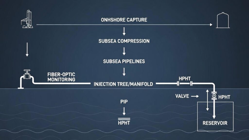
Figure 1: Subsea CCS Value Chain
(image: Flow diagram: onshore capture → subsea compression/pipelines → injection tree/manifold → reservoir storage, with labels for PIP, fiber-optic monitoring, and HPHT components.)
2. Carbon Capture Logistics: Offshore Transport & Injection Challenges
Logistics are the bottleneck moving millions of tonnes of CO₂ from capture sites to offshore storage safely and economically.
- Transport modes : Ships (LCO₂ carriers) for flexibility + subsea pipelines for high-volume, fixed routes.
- Liquefaction & buffering : Onshore terminals liquefy CO₂, buffer in tanks, then load carriers or pump to subsea lines.
- Subsea injection : High-pressure pumps push dense-phase CO₂ into depleted fields or saline aquifers. Challenges: hydrate formation, thermal stress, plume control.
- Scale : Projects target 1–10 Mtpa per site; logistics must match.
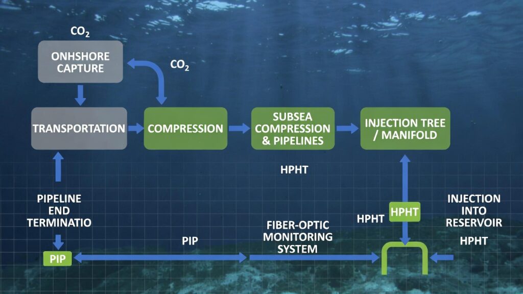
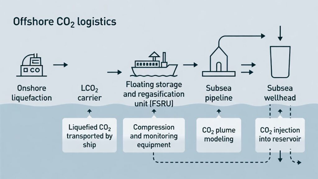
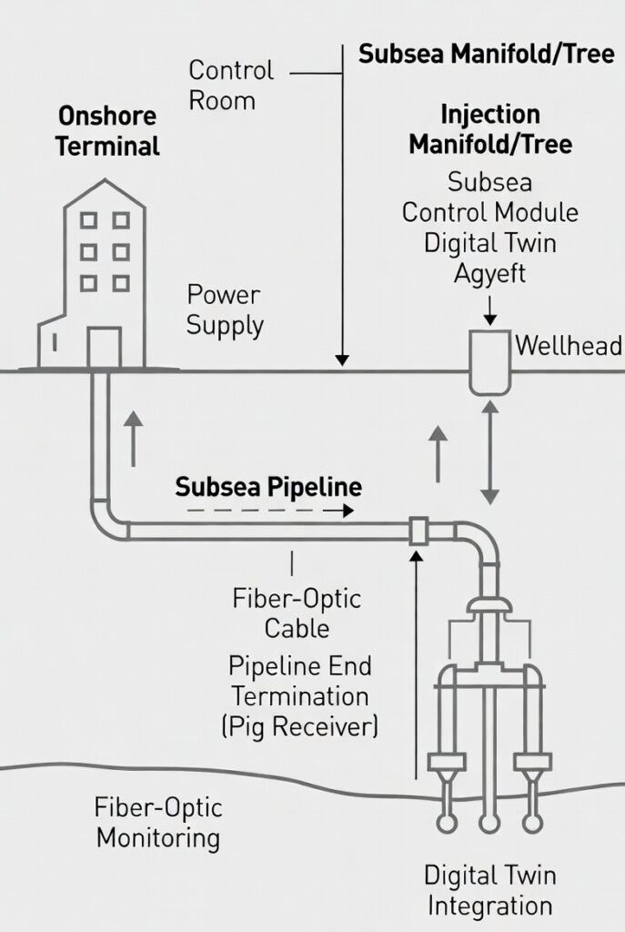
Figure 2: Offshore CO₂ Logistics & Injection Schematic
( image: Overview showing onshore liquefaction → LCO₂ carrier → floating terminal → subsea pipeline → injection wellhead, with callouts for compression, monitoring, and plume modeling.)
3. Real Case Studies: Subsea CCS in LNG ProjectsQatar North Field East (NFE)
- Scale: 32–33 MTPA new LNG (2026 start), up to 4–5 Mtpa CO₂ captured.
- Subsea role: ~500 km pipelines (trunk + intra-field) feed Ras Laffan. CCS uses subsea injection lines/manifolds to aquifers.
- Tech: PIP for thermal control, CRA materials, digital twins for plume/integrity monitoring. Reduces intensity ~25% vs. conventional LNG.
Mozambique LNG (TotalEnergies)
- Status: Restarted 2026, first LNG 2029 (13.1 MTPA).
- CCS plans: Capture CO₂ from high-CO₂ feed gas, subsea injection into depleted reservoirs.
- Subsea tech: HPHT flowlines/manifolds/risers to FPSO, future CCS injection lines/trees. Subsea compression for gas export (reduces flaring).
Northern Lights (Norway)
- Scale: 1.5 Mtpa Phase 1 (2024–2025), expanding to 5+ Mtpa.
- Subsea role: 110 km offshore pipeline from Kollsnes terminal to injection site in North Sea depleted reservoirs.
- Tech: Subsea manifolds/trees for injection, fiber-optic monitoring, digital twins for plume tracking.
Porthos (Netherlands)
- Scale: 2.5 Mtpa CO₂ from Rotterdam industry to depleted North Sea fields (2026 start).
- Subsea tech: Converted gas wells to CO₂ injection, subsea manifolds, remote control from shore.
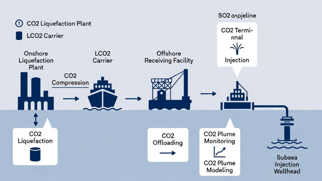
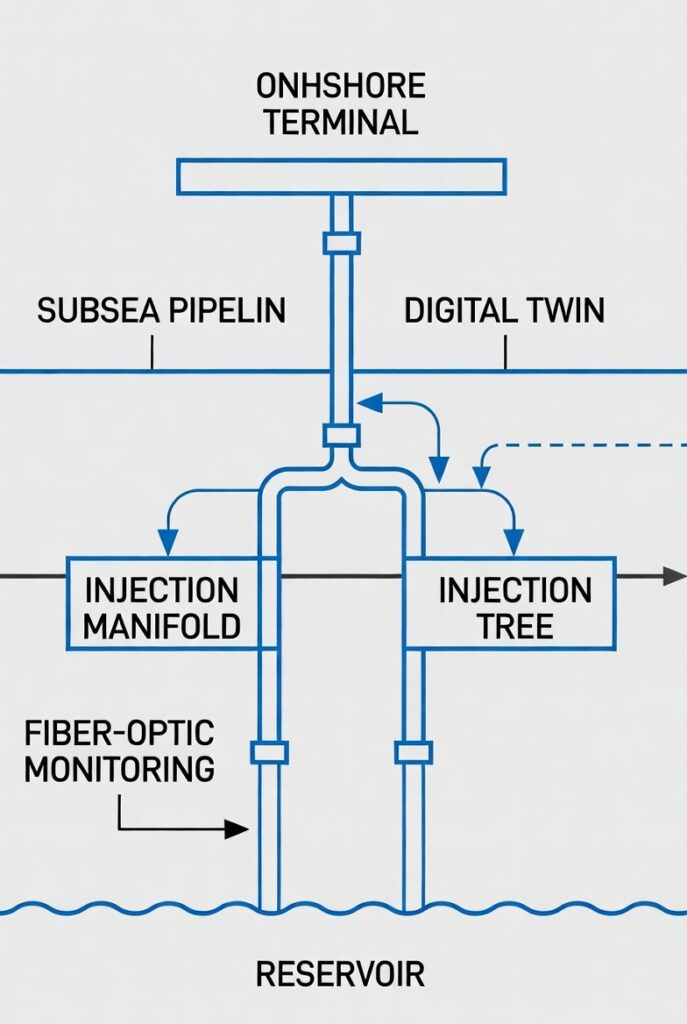
Figure 3: Northern Lights Subsea Injection Schematic
( image: Diagram showing onshore terminal → subsea pipeline → injection manifold/tree → reservoir, with labels for fiber-optic monitoring and digital twin.)
4. Floating Wind + CCS Synergies
Floating wind in deepwater basins (U.S. West Coast, North Sea) integrates with CCS via shared subsea infrastructure.
- Hywind Tampen (Norway): Floating wind powers oil platforms, reduces flaring/venting.
- Future hubs: Wind farms + CCS injection wells on shared moorings/subsea cables.
- Subsea tech: Dynamic cables for power export, subsea compression for CO₂ transport from wind-powered platforms.
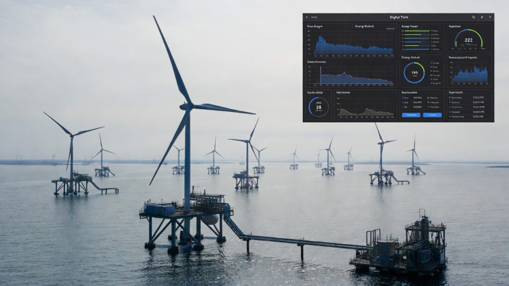
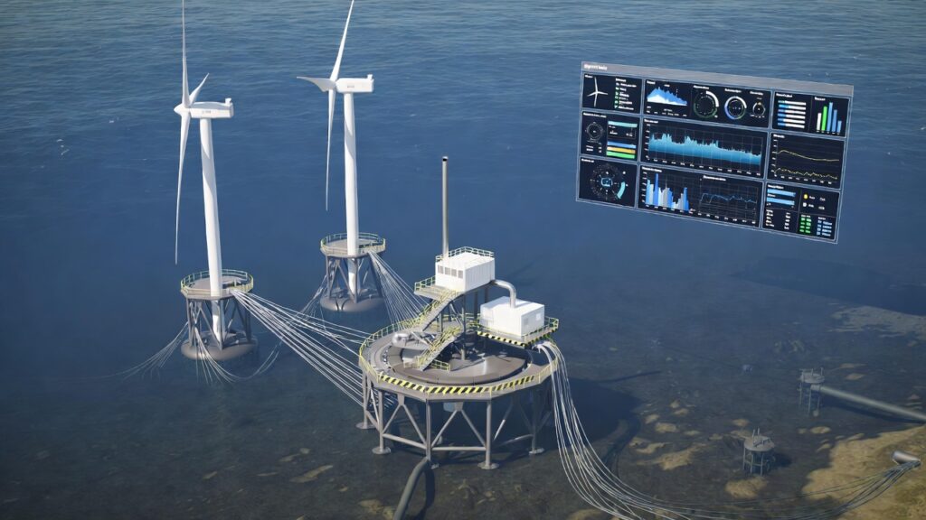
Figure 4: Hybrid Wind + CCS Hub Concept
( image: Floating wind turbines powering platform with CCS injection, shared subsea cable/pipeline, hydrogen module, digital twin dashboard.)
The Bottom Line
Subsea technology is the backbone of CCS in LNG: pipelines, compression, injection trees, and monitoring make offshore storage scalable and safe. Qatar NFE, Mozambique LNG, Northern Lights, and Porthos prove the model. Floating wind adds power and synergies.Engineers:
Which subsea CCS tech excites you most — PIP pipelines, subsea compression, or satellite/plume monitoring? Comment below or on LinkedIn. Subsea is leading the low-carbon LNG future.
Oko Immanuel
Subsea Engineering Specialist | Offshore Pipeline Insight ?