By Oko
Founder, Offshore Pipeline Insight
March 13, 2026
Dynamic cables represent a critical enabler for the expansion of floating offshore wind (FOW) farms into deeper waters, where traditional fixed-bottom foundations are impractical. Unlike static subsea cables that remain buried or fixed, dynamic cables often referred to as dynamic power cables or umbilicals must flex and endure constant motion induced by waves, currents, platform movements, and environmental loads. These high-voltage (HV) cables transmit power from floating wind turbines (FOWTs) to substations or shore, while also incorporating fiber optics for data and monitoring. As FOW scales to gigawatt levels in 2026, with projects like Hywind Tampen and Provence Grand Large operational, understanding dynamic cable design, analysis, and challenges is essential for reliability and cost reduction. This analysis draws on recent advancements, focusing on mechanical properties, configurations, fatigue, and real-world deployments.
Structure and Components of Dynamic Cables
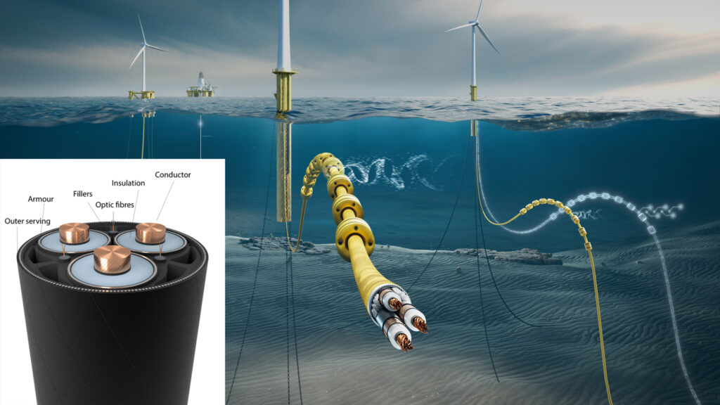
A typical dynamic cable is a multi-layered, helically wound assembly designed for flexibility and durability. Core elements include:
- Conductors: Usually copper or aluminum, helically stranded for bending resistance. They carry HV power (up to 145 kV in recent breakthroughs, qualified for 1,300m depths).
- Insulation: Cross-linked polyethylene (XLPE) or ethylene propylene rubber (EPR) to prevent electrical faults, with water-blocking layers to mitigate water tree growth—a defect where moisture ingress accelerates insulation breakdown.
- Armor and Sheath: Galvanized steel wires or synthetic fibers for mechanical protection against tension, torsion, and abrasion. Double-wire alternating coiling enhances twist resistance.
- Fillers and Optics: Integrated fiber optic cables for real-time monitoring (e.g., strain via distributed temperature sensing), fillers for structural integrity, and an outer polyethylene sheath for corrosion resistance.
These components exhibit “stick-slip” behavior, where internal layers alternately adhere and slide during bending or thermal cycles, potentially leading to wear. Here’s a cross-sectional diagram illustrating the layered structure:
Configurations and Global Layouts
Dynamic cables are configured to decouple platform motions from seabed interactions, minimizing fatigue. Common topologies include:
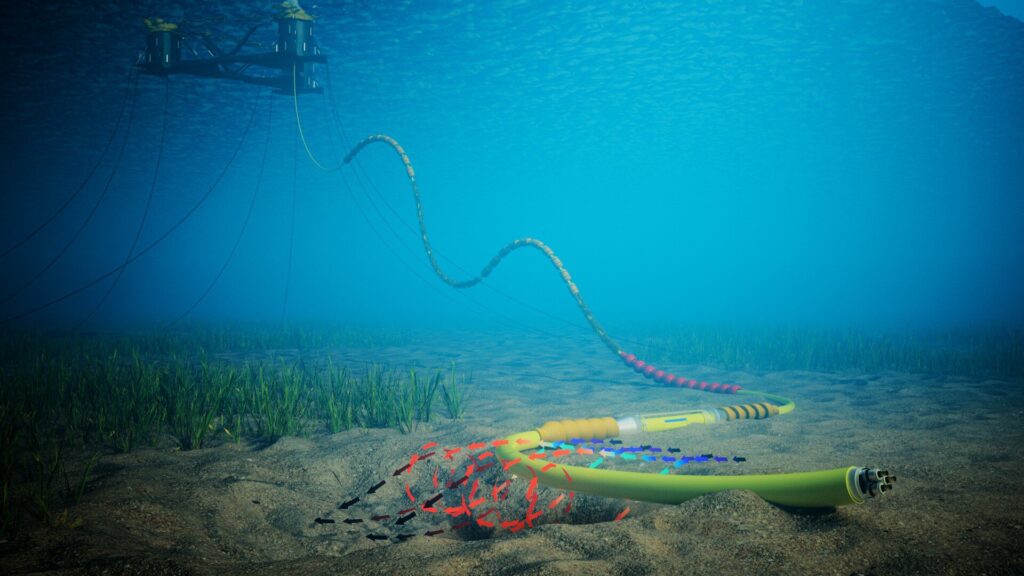
- Lazy-Wave: The most prevalent for FOW, featuring buoyancy modules to create an S-shaped sag in the water column, absorbing horizontal and vertical excursions. Ideal for depths up to 500m, it reduces top tension and touchdown loads.
- Double-Wave or W-Shaped: For ultra-deep waters (>1,000m), this adds extra loops to avoid excessive cable length, though it increases complexity and cost.
- Compliant or Tethered Wave: Used when uplift must be suppressed, incorporating ballast and anchors.
Ancillary equipment like bend stiffeners (at hang-off points), buoyancy/ballast modules, and bend restrictors protect against over bending. In inter-array setups, cables link FOWTs to floating substations; export cables then connect to shore, often transitioning to static sections. Platform type (spar-buoy, semi-submersible, or tension-leg) influences design—spars induce more heave, semis more pitch/roll.
This schematic shows a lazy-wave configuration in a FOW setup

Mechanical Analysis and Design Challenges
Design involves global (system-level) and local (cross-sectional) analyses using tools like OrcaFlex or ANSYS for hydrodynamic simulations. Key loads include:
- Tension and Bending: From platform offsets (near/far excursions), waves, and currents—vortex-induced vibrations (VIV) can amplify fatigue.
- Torsion and Twisting: Due to floater yaw, mitigated by helical armor.
- Environmental Factors: Seabed abrasion at touchdown, biofouling (adding weight and drag), and thermal cycling.
Quasi-static analysis excludes unfavorable setups early, while dynamic simulations calculate stress/strain cycles. Optimization considers cable offset designs, buoy positioning, and integration with moorings. Challenges: Higher voltages demand better water ingress prevention; costs are 2-3x static cables, though LCOE is dropping to $100-150/MWh.
Fatigue and Failure Mechanisms
Fatigue is the primary concern, with service lives targeted at 25+ years but often falling short (e.g., 2-10 years in some cases). Analysis uses strain-cycle curves and rainflow counting to estimate damage. Mechanisms include:
- Mechanical Fatigue: Cyclic bending/twisting erodes armor and conductors.
- Water Trees: Electrical stress and moisture cause tree-like defects in insulation, reducing dielectric strength.
- Wear and Fretting: Internal component friction; external from seabed contact.
- Biofouling: Marine growth increases drag, altering dynamics.
Standards like DNV-ST-0359 and IEC 63026 guide fatigue assessments, but gaps exist for HV dynamics—ongoing JIPs aim to refine criteria.
Installation and Real-World Deployments
Installation uses cable-laying vessels (CLVs) with dynamic positioning, often involving pre-laid moorings and ROVs for touchdown monitoring. Projects like Provence Grand Large (France) demonstrate successful inter-array installations in 2026
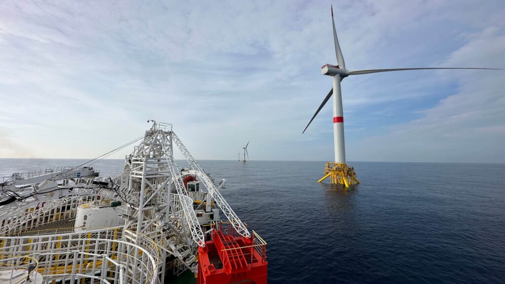
Risks include over-tensioning during lay; simulations and forced oscillation tests validate designs.
Future Outlook and Commercialization
With FOW projected at 56 GW by 2040, innovations focus on 66-132 kV arrays, hybrid oil-gas integrations, and AI-driven monitoring.
Challenges like supply chain bottlenecks and insurance hardening persist, but standardization will drive costs down.For offshore pros: How do dynamic cables impact pipeline integrity near FOW hubs? Share thoughts below! 