Oko Immanuel
Petroleum / Subsea Engineer
Founder, Offshore Pipeline Insight
Texas A&M Alumnus.
March 08, 2026
In 2026, onshore shale development continues to drive the majority of US oil and gas production growth, particularly in the Permian Basin, Eagle Ford, Bakken, and Haynesville. While much attention goes to horizontal drilling and multi-stage fracturing, the gathering and tie-in pipeline systems that connect land rigs and well pads to central processing facilities or trunk lines are often the unsung yet critical link in the production chain.
This technical blog examines the design, integrity challenges, and key lessons learned from onshore flow lines tie-ins in shale plays, with direct parallels to offshore subsea tiebacks.
1. Typical Land Rig to Gathering Line Configuration
A standard 2026 shale pad layout features:
- 8–24 horizontal wells drilled from a single pad using walking or skidding rigs.
- Individual wellhead flowlines (2–4 inch diameter, high-pressure-rated) connect each well to a central manifold or separator battery on the pad.
- From the battery, larger gathering flowlines (6–12 inch) transport multiphase production (oil, gas, water) to a central facility, compressor station, or trunk pipeline.
Key design considerations:
- High-pressure ratings (1,000–5,000 psi MAWP) for initial flowback and frac returns.
- Corrosion allowance and internal coatings (e.g., fusion-bonded epoxy) due to produced water and H₂S/CO₂.
- Expansion loops or flexible joints to accommodate thermal expansion and ground settlement.
- Pigging capability (launchers/receivers) for cleaning and inspection.
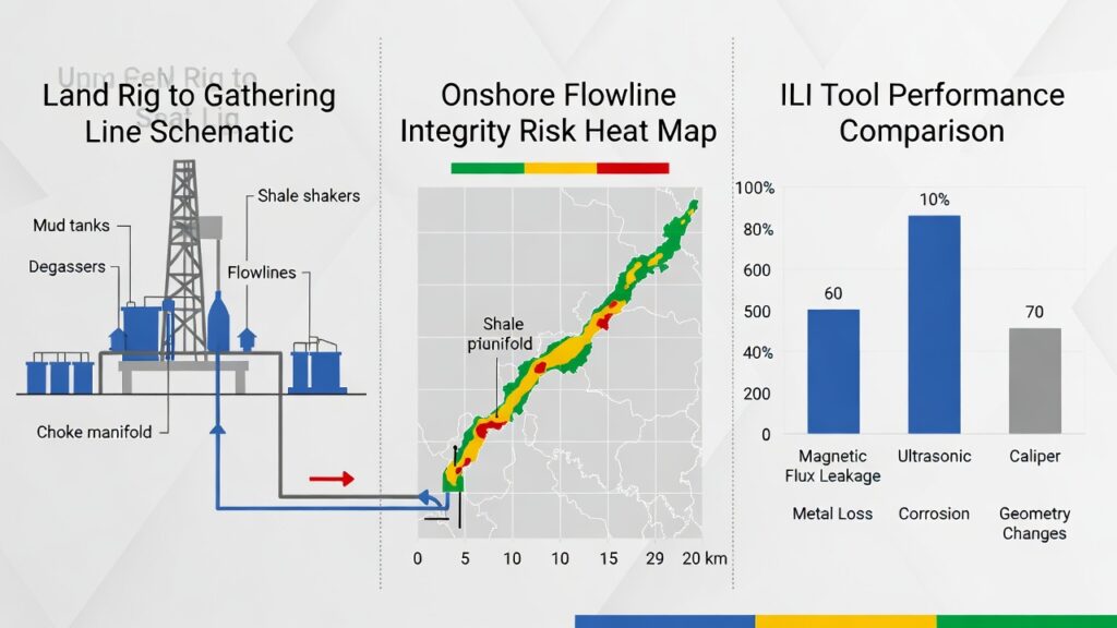
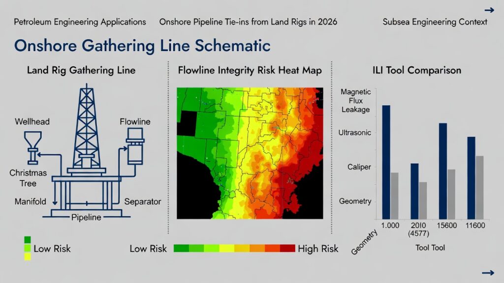
This schematic shows a typical land rig pad to gathering line configuration (multi-well pad → manifold → gathering flow lines central facility)
2. Onshore Flow lines Integrity Risk Heat Map
Integrity risks in onshore gathering flow lines differ from offshore export lines but share many root causes. The most common threats in 2026 shale plays include:
- Internal corrosion : Produced water with high chlorides, CO₂, H₂S, and bacteria (MIC).
- External corrosion : Soil corrosively, inadequate coating, cathodic protection shorts.
- Third-party damage : Construction, farming, or vehicle traffic.
- Erosion : High-velocity sand production during initial flow back.
- Fatigue : Cyclic pressure from intermittent well production or plunger lift.
This risk heat map illustrates relative failure probability and consequence in onshore shale gathering systems (2026 data trends):
3. In-Line Inspection (ILI) Tool Comparison for Onshore FlowlinesILI remains the gold standard for assessing gathering line integrity, but tool selection depends on diameter, wall thickness, bend radius, and product type.
| ILI Tool Type | Typical Diameter Range | Primary Detection Capability | Strengths in Shale Gathering Lines | Limitations |
|---|---|---|---|---|
| Magnetic Flux Leakage (MFL) | 4–24 inch | Metal loss (corrosion, gouges) | High-resolution corrosion mapping; cost-effective | Poor for axial cracks; requires clean pipe |
| Ultrasonic (UT) | 4–48 inch | Wall thickness, laminations, cracks | Accurate for pitting and small defects; no couplant needed in some tools | Sensitive to debris; slower run speed |
| Caliper (Geometry) | 4–48 inch | Dents, ovality, buckling | Essential for deformation detection post-frac hits | No corrosion info; must combine with MFL/UT |
| EMAT (Electro-Magnetic Acoustic Transducer) | 6–36 inch | Crack detection without couplant | Good for axial cracking in high-cycle lines | Higher cost; emerging in onshore use |
| Acoustic Emission (AE) | N/A (sensor-based) | Active crack growth monitoring | Real-time monitoring during production/frac | Not for baseline inspection; needs baseline data |
This chart compares ILI tool capabilities for onshore flowline integrity assessment in 2026
4.Tieback Lessons from Shale Plays (Transferable to Offshore)
- Modular manifold design : Central pad manifolds with isolation valves allow phased tie-in without shutting in producing wells : similar to subsea manifold modularity.
- Pigging & chemical inhibition : Regular pigging continuous corrosion inhibitor injection is now standard in wet gas/oil lines : direct parallel to offshore flow assurance.
- Real-time monitoring : Fiber-optic strain/temperature sensing on gathering lines detects third-party interference and SCP early : technology borrowed from offshore export lines.
- Risk-based inspection : Operators move from calendar-based to risk-based ILI frequency using probability of failure (PoF) and consequence of failure (CoF) models.
Closing Thoughts
Onshore gathering and tie-in pipelines in shale plays face intense corrosion, erosion, deformation, and third-party risks, yet many of the engineering solutions (ILI selection, chemical inhibition, real-time monitoring, risk-based integrity management) are directly transferable from offshore pipeline practices.
For pipeline and subsea engineers, the onshore shale environment is an excellent proving ground for technologies that later scale to deepwater tiebacks and export systems.
What onshore gathering line challenges are you seeing in your basin?
Drop a comment let’s share practical solutions!
Oko Immanuel
Petroleum / Subsea Engineer
Founder, Offshore Pipeline Insight
Texas A&M Alumnus
March 08, 2026